Wednesday, November 30, 2011

Airworthiness and other standards

       ተኽለሚካኤል ግርማይ  ተክሉ
http://tmaikleaviationengineering.webs.com/ 
http://flavors.me/teklemichael
For all aircraft designs, it is essential to know the airworthiness regulations that are appropriate. Each country applies its own regulations for the control of the design, manufacture, maintenance and operation of aircraft. This is done to safeguard its population from aircraft accidents. Many of these national regulations are similar to the European Joint Airworthiness Authority (JAA) and US-Federal Aviation Administration (FAA) rules. Each of these regulations contains specific operational requirements that must be adhered to if the aircraft is to be accepted by the technical authority (ultimately the national government from which the aircraft will operate). Airworthiness regulations always contain conditions that affect the design of the aircraft (e.g. for civil aircraft the minimum second segment climb gradient at take-off with one engine failed). Although airworthiness documents are not easy to read because they are legalistic in form, it is important that the design team understands all the implications relating to their design. Separate regulations apply to military and civil aircraft types and to different classes of aircraft (e.g. very light aircraft, gliders, heavy aircraft, etc.). It is also important to know what operational requirements apply to the aircraft (e.g. minimum number of flight crew, maintenance, servicing, reliability, etc.). The purchasers of the aircraft may also insist that particular performance guarantees are included in the sales contract (e.g. availability, timescale, fuel use, etc.). Obviously all the legal requirements are mandatory and must be met by the aircraft design. The design team must therefore be fully conversant with all such conditions

Monday, August 8, 2011

Introduction to Aircraft Design


The design method to be followed from the start of the project to the nominal end can be considered to fall into three main phases. These phases are illustrated bellow.
The conceptual design stage starts with the project brief and ends when the designers have found and refined a feasible baseline design layout. In some industrial organizations, this phase is referred to as the ‘feasibility study’. At the end of the preliminary design phase, a document is produced which contains a summary of the technical and geometric details known about the baseline design. This forms the initial draft of a document that will be subsequently revised to contain a thorough description of the aircraft. This is known as the aircraft ‘Type Specification’.
The next phase (project design) takes the aircraft configuration defined towards the end of the preliminary design phase and involves conducting detailed analysis to improve the technical confidence in the design. Wind tunnel tests and computational fluid dynamic analysis are used to refine the aerodynamic shape of the aircraft. Finite element analysis is used to understand the structural integrity. Stability and control analysis and simulations will be used to appreciate the flying characteristics. Mass and balance estimations will be performed in increasingly fine detail. Operational factors (cost, maintenance and marketing) and manufacturing processes will be investigated to determine what effects these may have on the final design layout. All these investigations will be done so that the company will be able to take a decision to ‘proceed to manufacture’. To do this requires knowledge that the aircraft and its novel features will perform as expected and will be capable of being manufactured in the timescales envisaged. The project design phase ends when either this decision has been taken or when the project is cancelled.
The third phase of the design process (detail design) starts when a decision to build the aircraft has been taken. In this phase, all the details of the aircraft are translated into drawings, manufacturing instructions and supply requests (subcontractor agreements and purchase orders). Progressively, throughout this phase, these instructions are released to the manufacturers.
At the end of the design process, the design team will have fully specified their design configuration and released all the drawings to the manufacturers. In reality, the design process never ends as the designers have responsibility for the aircraft throughout its operational life. This entails the issue of modifications that are found essential during service and any repairs and maintenance instructions that are necessary to keep the aircraft in an airworthy condition.

Project Activities for Aircraft Design


Excellence in design is one of the principal factors that enable a developed nation to stay competitive in a global economy.
The project design process is the means by which the competing factors and Constraints which affect the design are synthesized with the specialist analytical inputs to produce the overall configuration. 
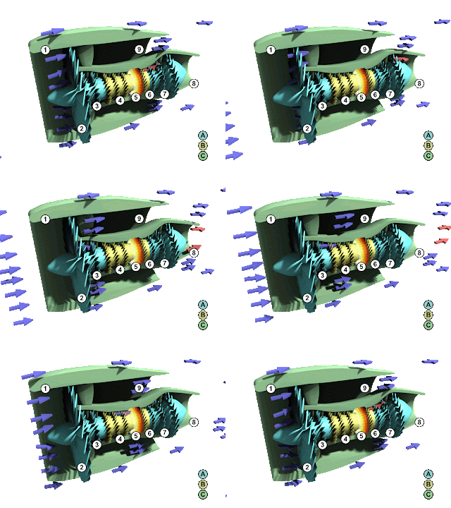
 Turbofan Engine

Conceptual Design


1. Perform the market survey to establish aircraft specifications from customer
Requirements; information is extracted from year-round exploratory work.
2. Lay out candidate aircraft configurations starting with fuselage, followed by
Wing, undercarriage, power plant, and so forth.
3. Establish wing parameters because they will acquire prime importance in syn-
thesizing aircraft design; the parameters include the wing reference area, aspect ratio, wing sweep, taper ratio, aerofoil thickness-to-chord ratio, wing twist, spar
Location, flap area, flight control, and wing location with respect to fuselage.
4. Initiate CAD 3D surface modeling.
5. Conduct preliminary CFD analysis to establish pressure distribution and loads
On aircraft.
6. Conduct preliminary wind-tunnel tests.
7. Determine preliminary weights and CG estimates.
8. Determine aircraft preliminary drag estimate.
9. Size aircraft and match engine.
10. Establish engine data.
11. Conduct preliminary aircraft and engine performance tests.
12. Freeze the configuration to one aircraft.
13. Lay out internal structures and arrange fuselage interior.
14. Complete mock-up drawings, construction, and initial evaluation
15. Complete the control system concept layout in CAD.
16. Complete the electrical/avionics systems concept layout in CAD
17. Complete the mechanical systems concept layout in CAD.
18. Complete the power plant installation concept in CAD.
19. Create a database for materials and parts.
20. Establish a plan for bought-out items and delivery schedule.
21. Plan for outsourcing, if applicable.
22. Provide the preliminary cost projection.
23. Obtain management’s go-ahead. Duct preliminary aircraft and engine performance tests.

Project Definition


1. Create integrated and component drawings in CAD.
2. Complete FEM stress analysis of all components (e.g., wing and fuselage).
3. Complete mock-up and final assessment.
4. Complete advanced CFD analysis.
5. Conduct wind-tunnel model testing and CFD substantiation.
6. Conduct flutter analysis.
7. Conduct extensive and final aircraft and engine performance tests.
8. Create detailed part design and issue manufacturing/production drawings in
CAD. This follows stress analyses of parts.
9. Perform aircraft stability and control analysis and control-surface sizing.
10. Finalize control system design in CAD.
11. Finalize electrical/avionics system design in CAD.
12. Finalize mechanical system design in CAD.
13. Finalize power plant installation design in CAD.
14. Produce jigs and tool design.
15. Plan for subcontracting, if applicable.
16. Place order for bought-out items and start receiving items.
17. Complete cost analysis.
18. Complete design review.
19. Continue customer dialogue and updating (no change in specifications).

Product Development


1. Complete detailed component design in CAD.
2. Complete stress analysis.
3. Complete CFD analysis.
4. Revise to final weights analysis.
5. Complete and issue all production drawings in CAD/CAM.
6. Complete production jigs and tools.
7. Complete parts manufacture and begin aircraft component sub assembly.
8. Finish receiving all bought-out items.
9. Complete standards, schedules, and checklists.
10. Finalize ground/flight test schedules.
11. Complete prototype shop status schedules.
12. Revise cost analysis.
13. Begin ground tests.
14. Complete design review.
15. Continue customer dialogue and updating (no change in specifications)

Testing and Certification


1. Complete final assembly and prototype equipping.
2. Complete ground and flight tests and analysis.
3. Review analysis and modify design, if required.
4. Complete overall design review.
5. Review cost estimate.
6. Complete customer dialogue and sales arrangement.
7. Continue design review and support.

Sunday, August 7, 2011

CATIA & CATIA distribution


CATIA solutions reduce development cycle time,


      improve quality and competitiveness
CATIA a multi-platform CAD/CAM/CAE
  • CATIA (Computer-Aided Three-Dimensional Interactive Application) is Dassault Systems pioneer brand and the cornerstone of the Dassault Systems product lifecycle managementsoftware  suite.
  • CATIAis a multi-platform CAD/CAM/CAE software.
  • Aerospace, Defense, and Automotive industries are just three that use CATIA as their primary design software’s.
  • The range of its capabilities allows CATIA to be applied in a wide variety of industries, such as aerospace, automotive, industrial machinery, electrical, electronics, shipbuilding, plant design, and consumer goods, including design for such diverse products as jewelry and clothing.
                      CATIA distribution:
  • More than 80 percent of large commercial and regional aircraft designers use CATIA. 
  • More than 80 percent of helicopter  designers use CATIA.
  • 19 of the top 30 automotive manufacturers use CATIA as their core design system. 
  • 9 of the 11 Formula One teams use CATIA for either chassis or engine design.
  • CATIA solutions reduce development cycle time, improvequality and competitiveness
  • CATIA to enhance creativity and innovation
  • CATIA is the only solution capable of addressing the complete product development process, from product concept specifications through product-in-service, in a fully integrated and associative manner.

CATIA in Aerospace industry.

FULLY MODELING  AN AIRPLANE THROUGH  CATIA V5

CATIA V5 &THE AIRPLANE.
  1. Several thousands of companies in multiple industries Worldwide have already chosen the virtual design capabilities of CATIA products to ensure their products real success.
  2. The world’s leading solution for Product Design and Innovation.
  3. CATIA is the leading solution for product success
  4. Aerospace – Airframe OEMs
  5. Aerospace –Aero-suppliers
  6. Aerospace –propulsion
  7. Aerospace –Missiles and Drones
  8. Aerospace –Space systems
  9. Aerospace –Defense

Saturday, August 6, 2011

Aircraft Design Overview.


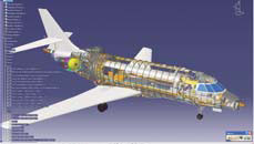
fully design of aircraft on CATIA.
 

  1. Aircraft Design Process
  2.  CATIA
  3. CAD/CAM and CAD/CAE models 
  4. FEA
  5. CFD

    Tuesday, August 2, 2011

    Aircraft Structural Loads


    Introduction

    Before the structure can be designed, we need to determine the loads that will be imposed on the aircraft. This section deals with the general issue of aircraft loads and how they are predicted at the early stages of the design process.

    Each part of the aircraft is subject to many different loads. In the final design of an aircraft structure, one might examine tens of thousands of loading conditions of which several hundred may be critical for some part of the airplane. In addition to the obvious loads such as wing bending moments due to aerodynamic lift, many other loads must be considered. These include items such as inertia relief, the weight and inertial forces that tend to reduce wing bending moments, landing loads and taxi-bump loads, pressurization cycles on the fuselage, local high pressures on floors due to high-heeled shoes, and many others.

    These loads are predicted using Navier-Stokes computations, wind tunnel tests, and other simulations. Static and dynamic load tests on structural components are carried out to assure that the predicted strength can be achieved. The definition of strength requirements for commercial aircraft is specified in FAR Part 25 and this section deals with those requirements in more detail.

    Some Definitions

    Many of the load requirements on aircraft are defined in terms of the load factor, n. The load factor is defined as the component of aerodynamic force perpendicular to the longitudinal axis divided by the aircraft weight. Assuming the angle of attack is not large, n = L/W. This is the effective perpendicular acceleration of the airplane in units of g, the acceleration due to gravity.

    The FAA establishes two kinds of load conditions:
    • Limit Loads are the maximum loads expected in service. FAR Part 25 (and most other regulations) specifies that there be no permanent deformation of the structure at limit load.

    • Ultimate loads are defined as the limit loads times a safety factor. In Part 25 the safety factor is specified as 1.5. For some research or military aircraft the safety factor is as low as 1.20, while composite sailplane manufacturers may use 1.75. The structure must be able to withstand the ultimate load for at least 3 seconds without failure.

    The remainder of this section deals with the computation of the limit load factor with additional detail on: